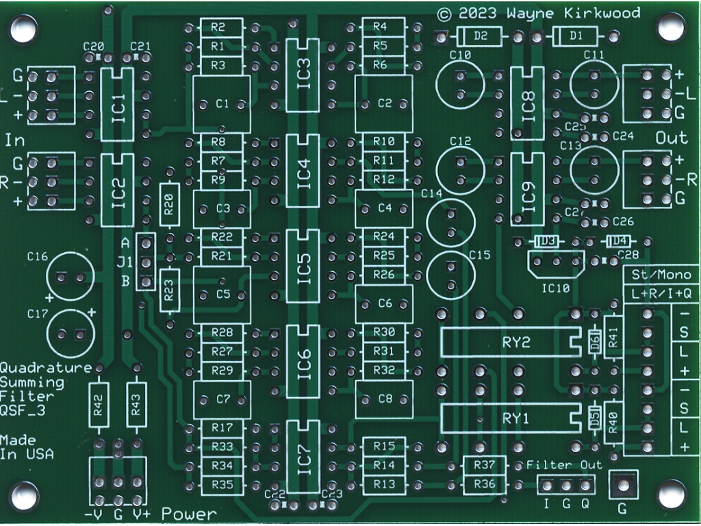
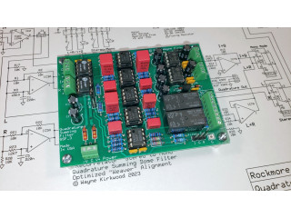
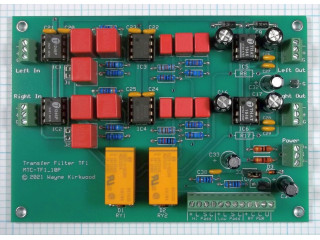
This is a bare unassembled circuit board and audio ICs for a "90°" Quadrature Summing Filter based on the design published in the Pro Audio Design Forum and prior work by Studer, Robert Dome and others. Included are (2) THAT1246, (2) THAT1646 and (5) NJM5532.
The KA-Electronics "Quadrature Summing Filter" board solves the problem of disappearing elements and audible changes when uncorrelated L-R difference information is lost during conventional L+R mono fold-down.
One common complaint solved by the Quadrature Summing Filter are keyboards whose stereo output changes when folded down to mono. Applications to studio recording include tracking and mix-down where a stereo keyboard is folded down to mono and then positioned in the mix by conventional in-console panning.
For mono mediums, such as AM broadcast or in-store background music, the Quadrature Summing Filter provides a product which sounds more like its' stereo counterpart and retains the original's signal power. For stereo compressor side chains, the Quadrature Summing Filter preserves the signal power allowing a single detector RMS or average-responding detector to have a more accurate estimate of actual level.
The Quadrature Summing Filter works by phase-shifting the Left and Right channels so they have a near-constant 90° difference between them throughout the audio spectrum. The phase-shifted paths, often called "I" and "Q," are then summed into "mono." The result is that in-polarity elements (L+R) and out-of-polarity elements (L-R) are summed into the final output with equal weight. L-R's contribution is equal to L+R's rather than L-R cancelling fully. The result is an output that sounds more like the input having nearly the same signal power and instrumental balance without the "sucked-out" sound of conventional mono.
Three Output Modes
The Quadrature summing filter accepts fully-balanced Left and Right inputs and provides the following three output modes:
Stereo forwards the Left and Right inputs to the Left and Right outputs providing buffered bypass.
Mono L+R adds the Left and Right channels with a -6 dB gain coefficient and forwards (L+R)/2 to the Left and Right outputs.
Mono I+Q adds the Left and Right channels in 90° quadrature with a -3 dB gain coefficient and forwards (I+Q)/1.4 to the Left and Right outputs.
Relay Mode Selection
One relay selects either L+R or I+Q Mono.
An additional relay allows selection between Stereo and Mono. Using the relays is possible to A/B compare any two sets of modes using a single button press.
Current-limited outputs are available to drive mode LEDs. An on-board 24V relay supply, not referenced to audio ground, is provided.
Auxillary I and Q Outputs
Buffered separate I and Q outputs are available on a header for instrumentation and "mono to stereo" width generation and instrumentation applications.
Balanced Inputs and Outputs
The inputs are fully-balanced using THAT 1246 line receivers. THAT 1646 OutSmarts® ICs drive the outputs.
Mechanical and Power Specifications
The board requires +/-15V at approximately 100 mA including external LEDs. No relay supply is required.
The board dimensions are: 3.7" x 2.75".
Mounting holes: #4/M3 0.125" dia on a 3.4" x 2.4" grid.
Audio Specifications
- Inputs: THAT1246. Input Impedance 24KΩ differential, 18KΩ common mode. Maximum input level +27 dBu.
- Outputs: THAT1646. Output impedance 50Ω nominal. Maximum output level +27 dBu.
- Aux I and Q Outputs: Buffered, output impedance 50Ω. Maximum output level +21 dBu.
- I and Q Differential phase: 90° ±3° 30 Hz -16 kHz.
- I+Q Summed Frequency Response: ±0.5 dB 30 Hz - 20 kHz for in or out-of-polarity inputs.
- Noise: Stereo -99 dBu, -101 dBu A-wtd DR 126 dB; Mono -100 dBu, I+Q -94 dBu -96 dBu A-wtd DR 121 dB.
- Gain: Stereo 0 dB; Mono 0 dB with equal in-polarity L and R inputs; I+Q 0 dB with equal in or out-of-polarity inputs.
- Distortion: Stereo, output level +20 dBu into 10KΩ load. 1 kHz THD 0.0001%, primarily HD3.
Note: Noise measurements are for a 20-20 kHz bandwidth and are unweighted unless specified. Maximum level specifications are for ±15V supplies.
Additional audio specifications and performance as they become available.
The construction thread for the Quadrature Summing Filter is featured in the Pro Audio Design Forum.
The Quadrature Summing Filter is sold as either a bare PC board, a "kit" including THAT1246, NE5532 and THAT1646 ICs, or an assembled and fully-tested module.
A Mouser Electronics Project Manager bill-of-materials is available for DIY builds of the Quadrature Summing Filter.
Quadrature "90°" Summing Filter, Bare PC Board and Audio ICs
- Brand: KA Electronics/Rockmore-Labs
- Product Code: QSF-PCB-IC
- Availability: In Stock
-
$59.95
Related Products
TDK 35W +/-15V +5V Triple Output Power Supply for Audio Use CUT35-5FF
The TDK CUT35-5FF a +/-15V bipolar power supply suitable for audio applications including the MS Mat..
$79.95
Quadrature "90°" Summing Filter, Assembled and Tested PC Board
This is an assembled and tested circuit board for a "90°" Quadrature Summing Filter based on the des..
$269.95
Quadrature "90°" Summing Filter, Bare PC Board
This is a bare unassembled circuit board for a "90°" Quadrature Summing Filter based on the design p..
$39.95
Transfer Filter, 18dB/Octave High and Low Pass, Neumann HT-75 Replacement, Bare PC Board
When only a steep filter will do. This is a bare unassembled circuit board for an 18 dB/Octave, high..
$39.95
Transfer Filter, 18dB/Octave High and Low Pass, Neumann HT-75 Replacement, Assembled and Tested PC Board
When only a steep filter will do. This is an assembled and tested circuit board for an 18 dB/Octave,..
$249.95

